Digital Archiving
Ever wondered what goes into post-production of photogrammetry scans? Ursula Ackah gives us a precise step-by-step guide of her photogrammetry process, digitising Toad from our collection for Steve Henderson, Damien Markey and the CHFA. See the results of Ursula’s scans over on our new Sketchfab account, click here.
Took pictures of Toad and Ratty in the basement studio with just overhead lighting and some daylight to one side.
Photographed each puppet front and back.
Because I took around 200 photos for each puppet in both positions, my photo count far exceeds the limit for the educational version of Autodesk ReCap Photo (100 per mesh).
It could be worth considering paying for the full license to be able to use the software’s full capability for this project. However, it’s also interesting to see what can be achieved with the 100 limit.
Initially, I choose only the photos which are in sharpest, fullest focus across the whole figure. Then I need to make sure I have comprehensive coverage. This won’t be fully apparent until the first full figure meshes are calculated and areas lacking detail can be observed.
I also took 40-50 shots of each of Toad’s hands, without altering or optimising position or lighting.
Results are surprisingly good given that undersides of the hands were obscured.
BACK VIEW
Scale Factor = Real / Digital Measurement.
Toad 2 Scale Factor 30cm / 2657.558 cm = 0.011288558895
I’m going to have to do this in more than one step.
30/1000 = 0.03 = 3%
Scale Factor = Real / Digital Measurement = 30cm/79.698cm = 0.37642 = 38%
Scale Factor = 30/30.328 = 0.989 = 99%
FRONT VIEW
Scale Factor = (21-1) cm / 1721.166 cm = 20/1721.166
Break up the process: 20/2000 = 0.01 = 1%
20/17.304 = 1.1558 = 116%
RISE PROJECT: TOAD
Toad by cosgrovehallfilmsarchive on Sketchfab
Process so far:
Photographed Toad and Ratty in 2 positions (front and back)
Selected 100 photos each for Toad’s front and back views
Uploaded these to ReCap Photo photogrammetry software to generate 2 meshes
Scaled these meshes in ReCap Photo using the ruler in shot
Deleted tabletop geometry in ReCap Photo
Exported the 2 meshes as OBJ files with 8K textures
Imported meshes into MeshLab; applied colour to vertices; aligned the meshes; exported.
Imported meshes and textures into Zbrush
Now in Zbrush I need to merge these meshes and this texture information to make a coherent whole.
I’ve found it’s best to treat Geometry and Colour as completely different processes.
(1) GEOMETRY
CLEAN UP
In Zbrush I need to get rid of the baggy geometry from the ‘underside’ of each mesh. This is the part of the mesh closest to the tabletop.
Do this using: mask > inverse > hide > delete hidden.
So now I have edits of the front and back meshes, where I’ve got rid of the baggy bits. Now I duplicate these and make sure my meshes are named clearly:
MERGE AND DYNAMESH
Front-Edit1 and Back-Edit1 are now merged; the result is renamed ‘Merge’. The two meshes are not joined – they just occupy the same active space for editing now.
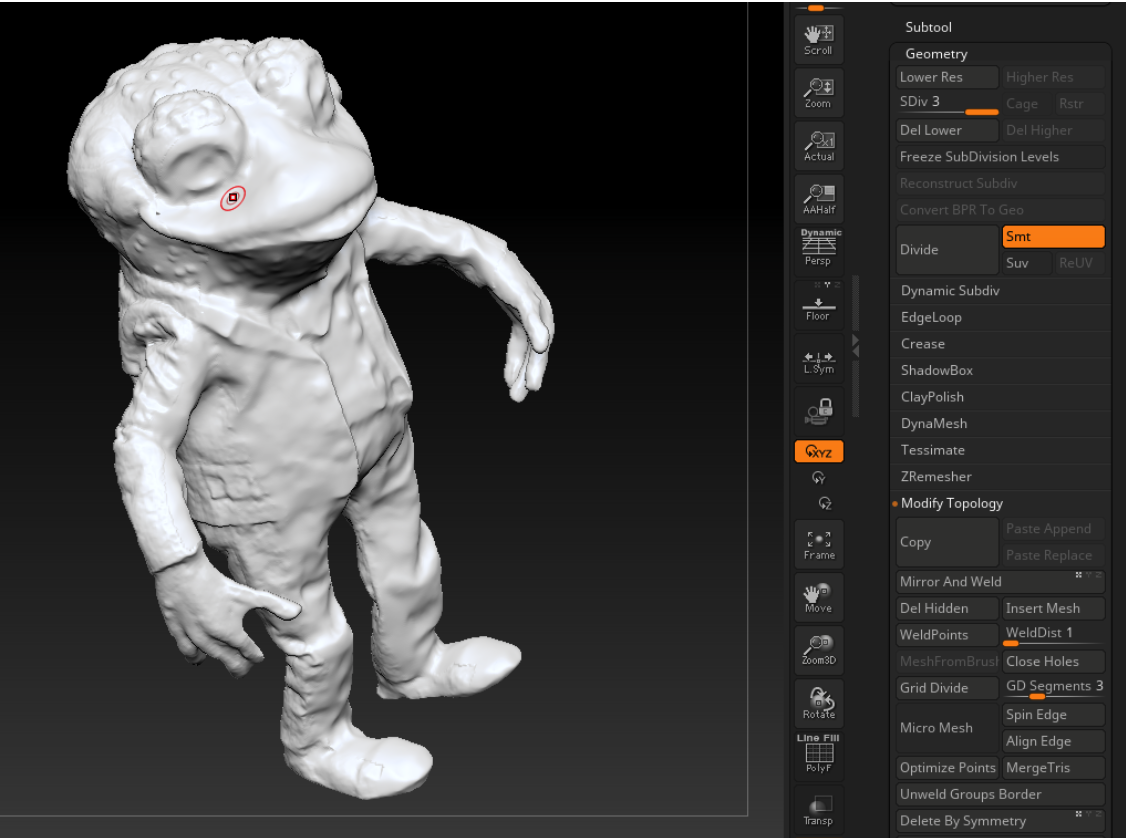
This subtool is duplicated and dynameshed, to generate a manifold geometry onto which I will project back the surface and colour detail.
So the result is generally good bar the webbing under the arms which might be eliminated if I use a higher res Dynamesh value, e.g. 256.
Not sure which way to go. Options are:
Eliminate webbing manually using edit tools
Undo and retry using 256 resolution instead of 128 (might crash based on how long 128 took to calculate)
Undo, export and use MeshLab Screened Poisson Surface Reconstruction instead
I’m going to try MeshLab.
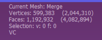
Merge Mesh Stats in MeshLab Screened Poisson Mesh Stats in MeshLab
Note the increase in size of the mesh in the numbers above. VC means ‘Vertex Colour’, i.e. this mesh is vertex coloured.
VQ means Vertex Quality but I’m not sure what that means! It seems to be something to do with Hausdorff Distance = distance between 2 meshes. The process analyses where duplicating mesh shells may be combined to produce a coherent continuous mesh so it must be to do with that.
Anyway, I export the new mesh from MeshLab and import back into Zbrush, and then do the Dynamesh. It takes a couple of seconds instead of many minutes to calculate, and gives a much better result:
I smooth out the dimple under his right arm and subdivide the mesh once.
PROJECT DETAIL BACK
Now I can start projecting geometric detail from the photogrammetry meshes back onto this new watertight mesh. Actually, it looks weird – I’m going to subdivide again.
Store Morph Target. Project Back-Edit onto the Dynamesh. First time I did this, I went straight on to projecting the Front-Edit but only then noticed problems with the hands. These need to be sorted out using Smooth Brush before doing the second projection.
Back projection done and ‘edges’ smoothed, especially on hands.
Store Morph Target > Front Project
Then smooth out the ‘edges’ (edges of projected geometry) using Morph and Smooth Brushes.
Then subdivde geometry again. Now he’s about 1.5 million quad polys. I probably don’t need more geometry detail on here except that there may be issues with the hands.
I’m wondering if it may be worth using those separate hand models I made?
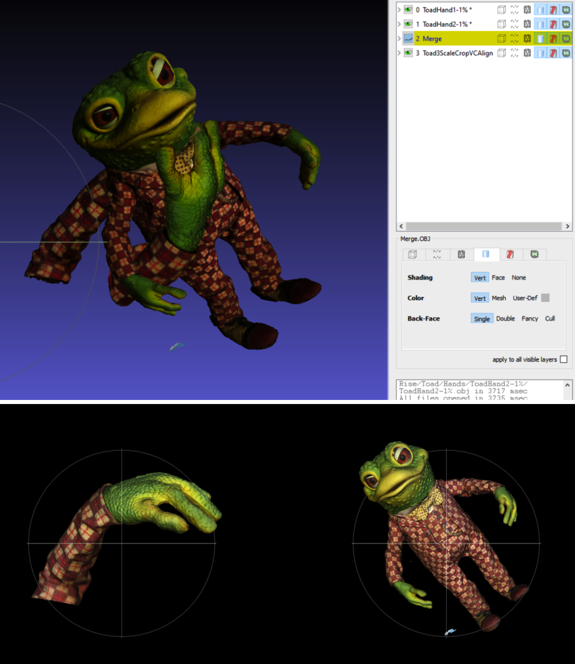
Method: Take the Front View back into MeshLab and align. I never scaled the hands down though, so they will be huge. So first, go into ReCap Photo, scale hands down to 1% of former scale. Export as OBJ. Import into MeshLab with the Front View.
Toad Front View in MeshLab plus 2 giant hands:
While doing the polypaint for the UVs I remembered 2 fingers were stuck together which had to be separated. This was done in ReCap Photo using the aligned vertex coloured hand model which was then imported into Zbrush and Booleaned onto the main model.
(2) COLOUR
Model needs to be UV’d. Copy the model, fill it with White and draw on it directly using Black to indicate the UV islands. Then use PolyGroupIt to create UV Map. Remember to specify 8K.
Once UV’d, the colour information can be projected on to the model from the scan meshes and saved out as texture files.
Create 2 texture map options using the projected data; export and blend them in Photoshop:
This didn’t work as well as I hoped due to some areas being in shadow on both images. I applied the new texture as Polypaint (vertex colour) and then masked problem areas on the model in Zbrush. I inverted the mask and projected original colour data from either the front or back view, whichever worked best, onto the problem areas. This solved most of the issues except for shadows on the body cast by the arms which are evident front and back.
I need to sort this in Photoshop, so I need new UVs so none of the UV island borders cross the area which need lightening in Photoshop.
I paint on a copy of the model to figure out which bits need to be UV islands for Photoshop blending.
These painted areas can be expanded and the Polypaint can be used to generate Polygroups, which in turn can be used to generate UV islands. Polypaint from Polygroups shows the UV islands I end up with. They really don’t matter much except for the areas I need to work on in Photoshop.
Project Polypaint onto this UV’d mode. Create texture from Polypaint. Clone and export texture.
For use on Sketchfab, the model was decimated to 10% polycount.
The texture image used is a 4K JPG.


